1. Channel Sounding, including Channel Sounding HCI Updates - distance measurement - CS uses an additional modulation scheme known as amplitude-shift keying (ASK) 2. LL Extended Feature Set - read all LE local/remote features 3. Decision-Based Advertising Filtering - Reduce the time it takes to receive an ADV by ignoring an uninterested ADV 4. Enhancements for ISOAL 5. Monitoring Advertisers - The host component of an observer device may instruct the Bluetooth LE controller to filter duplicate advertising packets. 6. Frame Space Update - Can change frame spacing (T_IFS) in LE Audio CIS(connected isochronic stream) - It was fixed at 150 µs in spec
Bluetooth는 Classic이라고 표현하는 BR/EDR과 low energy라고 주장하는 BLE로 크게 구분할 수 있다.
통신 속도와 관련하여 Basic Rate은 1Mb/s인데 EDR을 사용하면 2Mb/s, 3Mb/s를 사용할 수 있다.
BLE는 기본이 1Mb/s packet이고 LE2M를 사용하면 2Mb/s를 사용할 수있다.
그렇다면 LE Higher Data Throughput은 무엇인가?
말 그대로 Throughput을 높이겠다는 말이다. 얼마나? 7.5Mb/s까지.
좀 더 자세히 들어가면 2, 3, 4, 6, 7.5Mb/s를 지원한다.
어떻게?
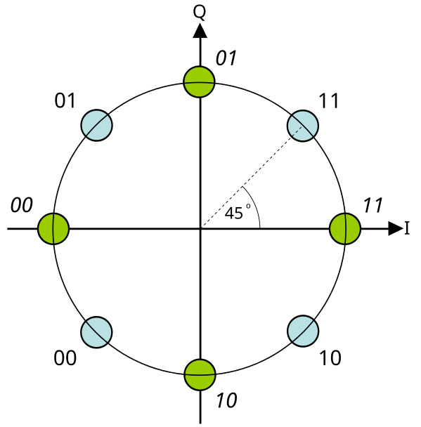
LE2M를 사용하는데 modulation을 변경하여 속도를 높이겠다고 한다. Bluetooth를 만드는 회사들이 Wi-Fi를 같이 만드는 회사가 많다보니 BT에서도 Wi-Fi에서 쓰던 기술들을 조금씩 추가하는 것 같다. 이번에 추가되는 Modulation이 Wi-Fi에서 사용하던 QAM 방식이다.
Name
HDT2
HDT3
HDT4
HDT6
HDT7.5
Effective bit rate
2 Mb/s
3 Mb/s
4 Mb/s
6 Mb/s
7.5 Mb/s
Modulation scheme
𝜋/4 QPSK
𝜋/4 QPSK
8PSK
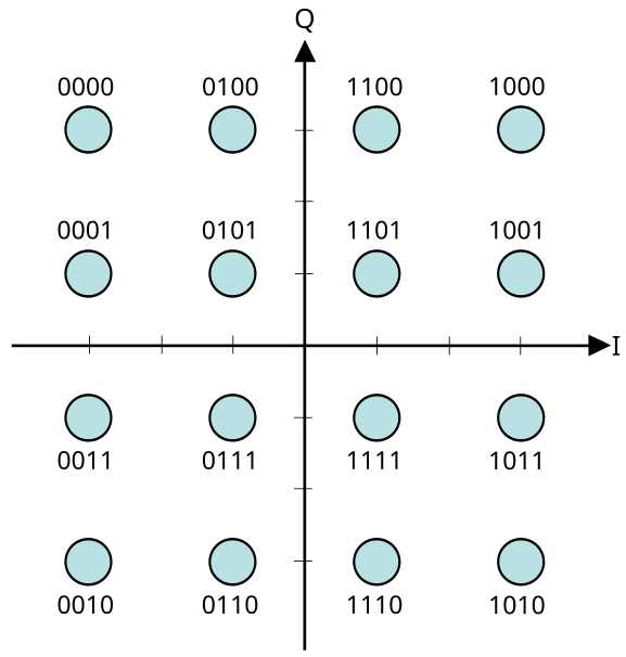
16QAM
16QAM
Symbol rate
2 Msym/s
2 Msym/s
2 Msym/s
2 Msym/s
2 Msym/s
𝜋/4 QPSK8PSK16QAM
한번에 인식할 수있는 data의 양이 엄청 늘어난다.
그렇다는 것은 깨질 확률도 늘어난다는 것이다. 그럼에도 이미 Wi-Fi에서 해봤던 방식이니 알아서 잘 만들겠지.
초기에 RSSI를 이용하여 대략적인 측량을 했고, AoA/AoD를 이용해 방향을 찾고, HADM으로 거리를 인식하려고 했으나 잘 되지는 않았다.
이번에 추가되는 Channel Sounding은 HADM의 추가 보완적인 형식이라고 생각된다.
Bluetooth SIG에서는 이를 이용하여 두가지 use case를 권장하고 있다.
Bluetooth Find My Solutions
Bluetooth Digital Key Solutions
Find My Solution은 Smart phone에서 제공하는 Find my device service나 Smarttihngs와도 다르다.
다만 user입장에서 볼 때 비슷한 기능을 수행하기 때문에 세부적인 것은 관심이 없다면 비슷한 기능이라고 볼 수도 있겠다. 하고자 하는 것은 device가 어디에 있는지 확인하는 것이다. Channel Sounding은 안테나 설계를 어떻게 하느냐에 따라 거리만 측정할 수도 있고 방향까지 측정할 수도 있다. 근처에 있는 내 device가 어디에 있는지 찾아내는 것이 이 solution의 내용이다.
Digital Key 역시 위치를 추적하는 것인데 device의 입장인 자동차가 User의 smart phone을 찾아내는 것이라 Find My Solution과는 반대 개념이다. RSSI로 거리를 측정하는 것은 정확도가 떨어지고, 단순 packet만 주고 받는 것은 MITM공격에 취약할 수 있어 CCC에서는 UWB를 추가하는 것을 권장하고 있다. Channel Sounding이 제대로 구현되면 UWB가 없어도 주변에 운전자 key가 있다는 것을 보장할 수 있다.
Bluetooth® Channel Sounding은 PBR(Phase-based Ranging)을 사용하여 두 가지 Bluetooth® LE 장치 간 HADM을 구현하며, 다른 채널의 수신 및 송신 무선 신호 간 위상 편이를 이용합니다. 주파수가 다른 두 개 이상의 신호를 이용하여 해당 신호 간 위상차(Δθ) 측정값에 따라 거리를 정밀 추정합니다.
UWB처럼 신호가 되돌아오는 파형의 이용하여 거리를 측정한다고 한다.
Phase-based Ranging (PBR) : initiator가 보내고 reflector가 응답한 것이 도착하면 위상차로 거리 계산
150 meters 거리를 측정할 수있고, 정밀도는 10cm까지 가능하다. (RSSI는 3~5m)
이를 위해 BLE에 Physical Layer를 추가하였다. => LE 2M 2BT PHY
이로써 BLE에는 LE 1M, LE 2M, and LE 2M 2BT PHY를 지원하게 된다.
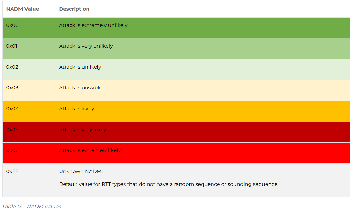
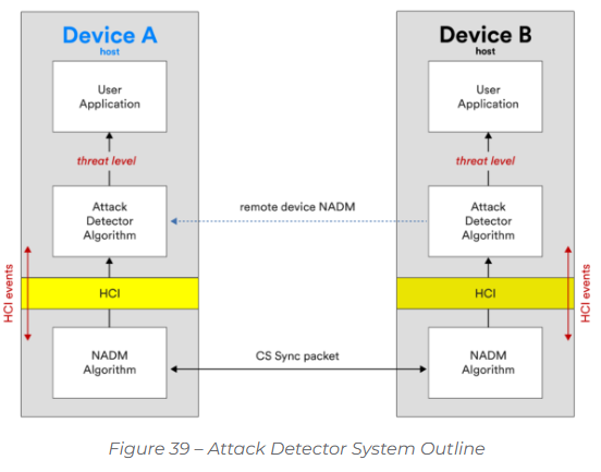
Channel Sounding 도중 공격에 대한 대응도 추가되어 있는데 NADM value라는 것이 추가되어 있다. 실제로 이것을 어떻게 검출하는지는 실제 동작을 확인해봐야 할 것 같다. 지금으로서는 단순히 이러한 것을 고려하고 있다는 정도만 알고 있다. Host에서 Attack Detector Algorithm을 돌리는데 어떻게 구현하는지가 명시되어 있지 않다.
(The algorithm which applications use for calculating distances is not specified by the Bluetooth Core Specification. Consequently, this is one area in which vendors can differentiate. Superior algorithms will produce superior results.)
Bluetooth controller is based on the evaluation of received signals against a reference signal definition the examination of the received signal for indicators of a possible attack such as unexpected bit transitions or phase adjustments.
Defined by the Bluetooth Core Specification and is called the Normalized Attack Detector Metric or NADM.
Device Roles
* Initiator : calculate the distance from itself to another device
* Reflector : peer device
* Either the Initiator or the Reflector can kick off the Bluetooth Channel Sounding procedure
Topology
* one-to-one topology
Antenna Arrays
* Devices that use Bluetooth Channel Sounding may include an antenna array.(Optional)
Applications
* Distances are calculated by the application layerconfiguration to establishing a Bluetooth Channel Sounding
Bluetooth SIG에서 매년 2번씩 Core version을 발표할 계획이기 때문에 더이상 Core버전으로 기능을 설명할 수 없게 되었다. 때문에 SIG에서는 기능 중심으로 표시하도록 권장하고 있다.
2. End-Use Product Guidance
End-use product companies are encouraged to utilize the communication elements listed below.Please note that while members often combine the Bluetooth wordmark with the Bluetooth®Core Specification version against which they qualified their product (e.g., Bluetooth 5.4) to indicate support for Bluetooth technology, the SIG does not endorse this, as it may lead to incorrect assumptions about supported Bluetooth functionality.
Communication ElementsRecommended terminology for use in promotional materials.Communication CriteriaProduct has completed the Bluetooth®Qualification Process and includes:
Communication ElementsRecommended terminology for use in promotional materials.Communication CriteriaProduct has completed the Bluetooth®Qualification Process and includes:
Bluetooth®Technology For communicating support for Bluetooth®technology.
Bluetooth®1
= No criteria beyond qualification
Bluetooth®Applications For communicating supported Bluetooth®applications as needed.
Classic Audio LE Audio AuracastTM ESL NLC
= Layer: A2DP or HFP = Layer: TMAP or HAP = Layer: PBP3 = Layer: ESLP = Layer: ALSNLCP, BLCNLCP, BSSNLCP, DICNLCP, ENMNLCP, or OCSNLCP
Bluetooth®Core Version4 For communicating the Bluetooth®Core Specification against which the product was qualified, if applicable.
= ICS: CORE 1/50 or 2/50 = ICS: CORE 1/51 or 2/51 = ICS: CORE 1/52 or 2/52 = ICS: CORE 1/53 or 2/53 = ICS: CORE 1/54 or 2/54 = ICS: CORE 1/60 or 2/60
ELS : Electronic Shelf Labels 마트에 자주 보이는 전자 가격표
NLC : Networked Lighting Control 전등
3. Enabling Technology Product guidance
Enabling technology product companiesare encouraged toutilizethe followingcommunication elementslisted below.Please note thatwhilemembersoftencombinethe Bluetoothwordmarkwith the Bluetooth®Core Specification versionagainst which they qualified their product(e.g., Bluetooth6.0)toindicatesupport for Bluetooth technology, the SIG does not endorse this, as itmayleadto incorrect assumptions about supportedBluetooth functionality.
Communication ElementsRecommended terminology for use in promotional materials.Communication CriteriaProduct has completed the Bluetooth®Qualification Process and includes:
Bluetooth®Technology For communicating support for Bluetooth®technology.
= No criteria beyond qualification = ICS: CORE 30/1 or 30/3 = ICS: CORE 30/2 or 30/3 = ICS: CORE 30/3
Bluetooth®Features For communicating supported Bluetooth®features as needed.
Channel Sounding LE 2M LE Coded Direction Finding LE Power Control Isochronous Channels Extended Advertising Periodic Advertising Periodic Advertising with Responses LE Secure Connections Classic Audio LE Audio Mesh Networking
= ICS: CS 1/1 or 1/2 = ICS: RFPHY 1/4 = ICS: RFPHY 1/7 = ICS: RFPHY 1/9 or 1/11 = ICS: LL 9/37 = ICS: LL 9/31, 9/32, or 9/33 = ICS: LL 9/41 = ICS: LL 9/42 = ICS: LL 9/49 or 9/50 = ICS: GAP 27b/5 or 37b/5 = Layer: A2DP or HFP = Layer: BAP = Layer: MESH or MMDL
Bluetooth®Profiles For communicating supported Bluetooth®profiles as needed.
Advanced Audio Distribution Profile Hands-Free Profile Telephony and Media Audio Profile Hearing Access Profile Public Broadcast Profile Ranging Profile Generic Health Sensor Profile Electronic Shelf Label Profile Ambient Light Sensor NLC Profile Basic Lightness Controller NLC Profile Basic Scene Selector NLC Profile Dimming Control NLC Profile Energy Monitor NLC Profile Occupancy Sensor NLC Profile